The Sun which known unlimited energy delivers to us in two main forms: heat and light. There are two main types of solar power systems, namely, solar thermal systems that trap heat to warm up water and solar system PV that convert sunlight directly into electricity. The word photovoltaic (PV) comes from “photo,” meaning light, and “voltaic,” which refers to producing electricity.
1. Concept of solar panels, how do they generate electricity?
1.1 PV Technology
Photovoltaic (PV) cells are made of at least two layers of semiconducting material, usually silicon, doped with special additives. One layer has a positive charge, the other negative. Light falling on the cell creates an electric field across the layers, causing electricity to flow. The intensity of the light determines the amount of electrical power each cell generates.
 Note that PV cell is just a converter, changing light energy into electricity. It is not a storage device, like a battery 😛
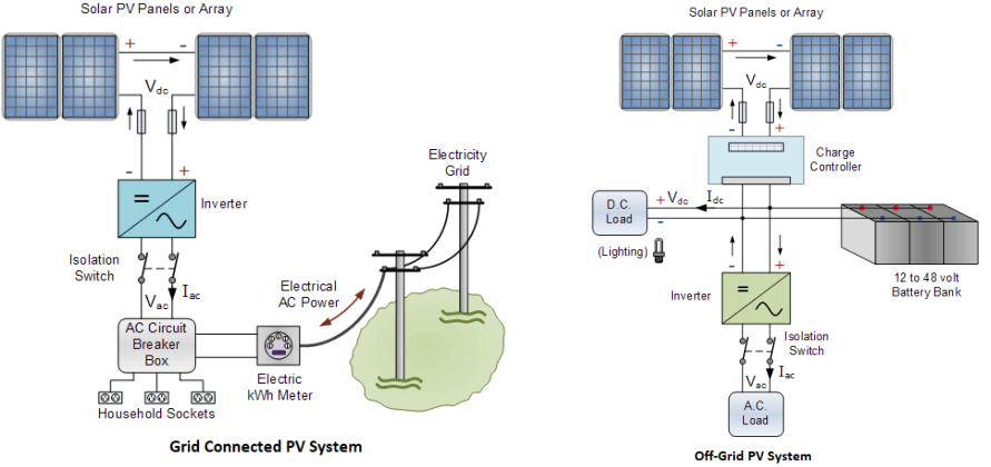
A basic unit of a PV system called a Solar Cell. All other concepts are presented in figure below:

2. Solar System Configuarations
There are two main configurations of Solar PV systems: Grid-connected (or grid-tied) and Offgrid (or standalone) solar PV systems.
2.1.Grid Connected PV Systems
If there is enough electricity flowing in from your PV system, no electricity will flow in from the utility. If your system is generating more power than you are using, the excess will be exported into the energy utility grid, turning your meter backwards. During the times when the PV system isn’t producing electricity, such as at night, the power grid will supply all the home’s demand .
2.2 Standalone PV Systems
Off-grid PV systems have no connection to an electricity grid. A simple standalone PV system is an automatic solar system that produces electrical power to charge banks of batteries during the day for use at night when the suns energy is unavailable. Deep cycle lead acid batteries are generally used to store the solar power generated by the PV panels, and then discharge the power when energy is required. Deep cycle batteries are not only rechargeable, but they are designed to be repeatedly discharged almost all the way down to a very low charge.
A charge controller is connected in between the solar panels and the batteries. The charge controller operates automatically and ensures that the maximum output of the solar panels is directed to charge the batteries without over charging or damaging them.
An inverter is needed to convert the DC power generated into AC power for use in appliances
Standalone PV systems are ideal for where frequent power outages seriously affect production or far away places, where fee for supply grid electrical very expensive more than PV installing cost.
3. Overview of Photovoltaic Performance
3.1 Solar Irradiance
It is a measure of how much sunlight intensity or power in Watts per square meter falling on a flat surface or you are getting at your location. Because weather conditions are somewhat similar over the years, it is possible to predict the average monthly and annual energy production of a system using historic, standardized weather data.
3.2 Solar Insolation
Solar insolation is a measure of solar irradiance reaches a PV surface at any given time. Solar energy available in a given location is expressed as kWh/m2/day.
For example, if solar radiation for a location is 5kWh/m2/day. Now, if you install 1kW solar panel on that location, it will produce 1kW x 5h = 5kWh energy per day without considering any losses.
3.3 Sun Angle and PV Orientation
The direction that a solar panel faces is referred to as its orientation. The orientation of the solar array is very important as it affects the amount of sunlight hitting the array and hence the amount of power the array will produce. If due to structure of building where it is difficult for the panels to face the South, then it can be oriented to the East or West but under no circumstances to the North as its efficiency will be then very limited. The highest efficiency of a PV module or peak power occurs when its surface is perpendicular to the sun’s rays 
3.4 Electrical Characteristics
The solar power produced by a PV solar cell is called DC same as from battery. Most PV solar cells produce a open circuit (no-load) voltage of about 0,5 to 0,6V. This output voltage depends very much on the load current demands. PV solar cell have a limted current, this is called the maximum deliverable current ${I_{\max }}$. The ${I_{\max }}$ value of a single photovoltaic solar cell depends upon the size or surface area of the cell, the amount of direct sunlight hitting the cell, its efficiency of converting this solar power into a current and of course the type of semiconductor material that the cell is manufactured .
Most commercially available photovoltaic solar cells have solar power ratings which indicate the maximum deliverable solar power, ${P_{\max }}$ that the cell can provide in Wats and is equal to the product of the cell voltage V multiplied by the maximum cell current I and is given as:
${P_{\max }} = {V_{out}}*{I_{\max }}$
3.5 Photovoltaic I-V Characteristics Curves
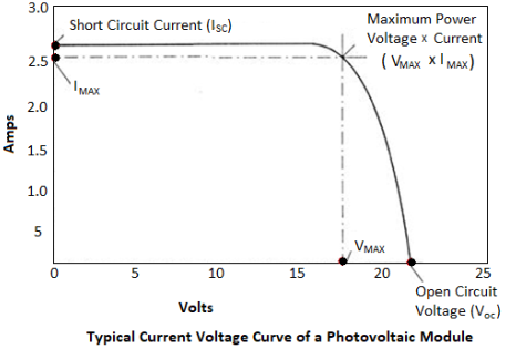
Manufacturers of the photovoltaic solar cells produce current-voltage (I-V) curves, which gives the current and voltage at which the photovoltaic cell generates the maximum power output and are based on the cell being under standard conditions of sunlight and temperature
3.6 Short Circuit Current (${I_{sc}}$)
A photovoltaic module will produce its maximum current when there is essentially no resistance in the circuit. This would be a short circuit between its positive and negative terminals. This maximum current is called the short circuit current (Isc). This value is higher than Imax which relates to the normal operating circuit current
3.7 Open Circuit Voltage (${V_{oc}}$)
Open circuit voltage (${V_{oc}}$) means that the PV cell is not connected to any external load and is therefore not producing any current flow (an open circuit condition). This value depends upon the number of PV panels connected in series
3.8 Maximum Power (${P_{\max }}$)
This relates to the point where the power supplied by the array that is connected to the load (batteries, inverters) is at its maximum value, where ${P_{\max }} = {I_{\max }}*{V_{\max }}$. The maximum power point of a photovoltaic array is measured in Watts (W).
3.9 Fill Factor (FF)
The fill factor is the ratio of maximum power output (Pmax) to the result of the open-circuit voltage times the short-circuit current, (${V_{oc}}*{I_{sc}}$). The relationship is:\[FF = \frac{{{P_{\max }}}}{{{V_{oc}}*{I_{sc}}}} = \frac{{{I_{\max }}*{V_{\max }}}}{{{V_{oc}}*{I_{sc}}}}\]
The FF factor gives an idea of the quality of the array. The closer the fill factor to 1 (unity), the more power the array can provide. Typical values are between 0,7 and 0,8.
3.10 Solar Intensity
The amount of sunlight falling onto the face of the PV cell affects its output. The more sunlight entering the cell, the more current it produces. The voltage will remain the same.
Dirt and dust can accumulate on the solar module surface, blocking some of the sunlight and reducing output. A typical annual dust reduction factor to use is 93% or 0,93.
3.11 Temperature
PV cell performance declines at higher cell temperatures. The operating voltage drops with increasing cell temperature. So, in full sun the output voltage reduces by about 5% for every 25°C increase in cell temperature. Most thin film technologies have a lower negative temperature coefficient compared to crystalline technologies. In other words, they tend to lose less of their rated capacity as temperature rises

3.12 PV Module Efficiency & De-rating Factors
The De-rating factors consider the loss factors for solar power. All the losses factor have been listed bellow Figure:
 Ex: On a clear sunny day, a ${\rm{1kWp}}$ PV array received 6 Peak Sun Hours (PSH). Expected output can be determined as follows:
Peak Power Output x Peak Sun Hours = Expected Output 1kW x 6PSH = 6kWh
But due to the infuluence of loss factors, the expected output will reduce follow this:
Expected Output = Peak Sun Hours x Peak Power Output x Total derating factor
= 1kWp*6*60%=6*60%=3,6kWh
3.13 Performance degradation over life cycle
The performance of a PV module will decrease over time. Generally, degradation of a good quality module is about 20% during the module life of 25 years and 0.7% to 1% per year.
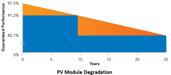 Return to above example and considering degradation of module as per the indicative profile above, energy generation:
= 3.28kWh per day (on 10th year)
= 2.90kWh per day (on 25th year)
3.14 PV Array Sizing
The equation that may be used to size a stand-alone PV system is:\[{W_{pv}} = \frac{E}{{PSH*{\eta _{sys}}}}\]
Where:
– ${W_{pv}}$: Peak wattage of the array
– E= daily energy requirement
– PSH: Average daily number of Peak Sun Hours in designed month
– ${{\eta _{sys}}}$: total system efficiency
Note: The month that the system is designed is the month of the lowest average daily solar during the operation period of the system.
The number of peak hours is for orientation of the PV array. If the only information available is for solar radiation in a horizontal plane, then a tilt and orientation correction factor should be applied.
3.15 Wiring Solar Panels in a Series Circuit
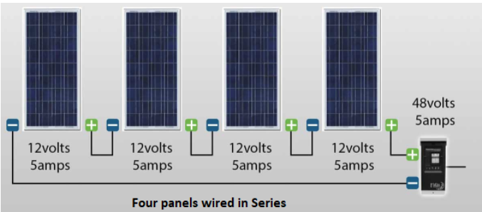
Connect the positive terminal of the first solar panel to the negative terminal of the next one. Example: If you had 4 solar panels in a series and each was rated at 12 volts and 5 amps, the entire array would be 48 volts at 5 amps.
3.16 Wiring Solar Panels in a Parallel Circuit
Connect all the positive terminals of all the solar panels together, and all the negative terminals of all the panels together.
Example: If you had 4 solar panels in parallel and each was rated at 12 volts and 5 amps, the entire array would be 12 volts at 20 amps.

4. Inverter
Inverters which still know as convert direct DC current (from batteries or solar panel) into alterating current current (AC).
They may be classified into 2 types:
a. Stand-alone Inverters used in isolated systems not coneected to the grid. The inverter draws its DC engery from batteries charged by solar arrays and supply AC energy to the load.
b. Battery Backup Inverters: These are special inverters which are designed to draw energy from a battery, manage the battery charge via an onboard charger. These inverters are capable of supplying AC energy to selected loads during a utility outage.
When specifying an inverter, it is necessary to consider requirements of both the DC input and the AC output.
a. For a grid connected PV system, the DC input power rating of the inverter should be selected to match the PV panel or array.
b. For standalone systems, the power inverters are selected based on the input battery voltage, maximum load, the maximum surge required, variations in voltage and any optional features needed.
4.1 Standalone Inverters
Stand-alone inverters typically operate at 12, 24, 48 VDC input and create 110 or 220VAC at 50Hz. The selection of the inverter input voltage is an important decision.
4.1.1 Efficiency
Almost inverters have peak efficiencies of 92% to 94%, as rated by their manufacturers. Actual field conditions usually result in overall efficiencies of about 88% to 92%
4.1.2 Surge Capacity
Most inverters can exceed their rated power for limited periods of time (seconds). Surge requirements of specific loads should be determined or measured. Some transformers and AC motors require starting currents several times their operating level for several seconds.
4.1.3 Voltage Protection
The inverter can be damaged if DC input voltage levels are exceeded. Remember, battery voltage can far exceed nominal if the battery is overcharged. A 12-volt battery may reach 16 volts or more and this could damage some inverters. Many inverters have sensing circuits that will disconnect the unit from the battery if specified voltage limits are exceeded.
4.2 Grid Conntected Inverter
For grid-connection, the inverter must have the words “Utility-Interactive” printed directly on the listing label. Here are some guidelines:
4.2.1 Voltage input
The inverter’s DC voltage input window must match the nominal voltage of the solar array, usually 12, 24 or 48 volts for battery-based systems.
4.2.2 Surge Capacity
The starting surge of equipment such as motors is not a consideration in sizing grid-connected inverters. When starting, a motor may draw as much as seven times its rated wattage. For gridconnected systems, this start-up surge is automatically drawn from the grid.
4.2.3 Efficiency
Modern inverters have peak efficiencies of 92 percent to 94 percent, as rated by their manufacturers. Actual field conditions usually result in overall efficiencies of about 88 percent to 92 percent. Inverters for battery-based systems have slightly lower efficiencies.
4.2.4 Maximum Power Point Tracking (MPPT)
Modern non-battery-based inverters include maximum power point tracking. MPPT automatically adjusts system voltage such that the PV array operates at its maximum power point. For battery-based systems, this feature has recently been incorporated into better charge controllers.
5. Charge Controllers
A charge controller is only necessary in standalone systems with battery back-up. The primary function of a charge controller is to prevent overcharging of the batteries or limiting excessive discharge. Overcharging can boil the electrolyte from the battery and cause failure and in case the battery be discharged too much cause sooner battery break. The controller is a critical component in the PV system. A controller’s funtion is to control the system depending on the batter “State-of-charge” (SOC). When the battery nears full, the controller will switches off all or part of solar array. When the battery is discharged below a preset level, some or entire load is disconnected. Most controllers use a measurement of battery voltage to estimate the state-of-charge. Even many controllers have a temperature probe to measure battery temperature for improving the SOC esimate.
Nowaday, almost modern charge controllers incorporate maximum power point tracking (MPPT), which optimizes the output of Solar array, increasing the energy it produces. The major principle of MPPT is to find at most efficient voltage of PV module or array. This voltage is matched to the battery voltage, in order to insure maximum charge current. The PV module or string of modules maximum power point defines the current that should be drawn from the PV in order to get the most possible power.
5.1 Charge Regulation
There are two main charging regulation methods:
- Switching regulation. The controller leads all available PV current to the battery during charging. If reaching the maximum allowable voltage, the controller switches off the charging current. When the voltage falls, the current is reconnected.
- Constant voltage regulation. The controller can modify the voltage setpoint charging by sensing the battery condition in order to avoid breaking.
5.2 Select of Charge Controllers
Charge controllers are selected based on:
a. PV array voltage – The controller’s DC voltage input must match the nominal voltage of the solar array.
b. PV array current – The controller must be sized to handle the maximum current produced by the PV array.
c. Compatible with batteries: The charge controller must be selected to deliver the charging current appropriate for the type of batteries used in the system. Most PV systems use deep-cycle lead-acid batteries of either the flooded type or the sealed type. Sealed batteries need to be regulated to a slightly lower voltage than flooded batteries or they will dry out and be ruined. For example, on a 12V system, flooded lead-acid batteries have a voltage of 14.6V to 15.0V when fully charged, while sealed lead-acid batteries are fully charged at 14.1 V. Refer to the battery manufacturer for the charging requirements of batteries. Never use a controller that is not intended for your type of battery.
6. Batteries
Batteries accumulate energy created by the PV system and store it to be used at night or when there is no other energy input. The battery storage system can provide a relatively constant power source, even when the photovoltaic system is disconnected for repair and maintenance or producing minimal power in periods of reduced sunlight.
Battery storage capacity is rated in ampere hours, which is the current delivered by the battery over a set number of hours, at a normal voltage, and at a temperature of 25ºC. Most PV systems use lead acid batteries or conventional flooded batteries. Nickel cadmium batteries are usually the best option when very high reliability is required.
6.1 Batteries Types and Classification
Types of batteries commonly used in PV systems are:
a. Lead-acid batteries: Flooded (wet battery) and Sealed-Gel cell (dry battery)
b. Alkaline batteries: Nickel-cadmium and Nickel-iron
6.2 Lead Acid Batteries
Lead-acid batteries are most common in PV systems. Lead battery cells consist of two lead plates immersed in dilute sulphuric acid which creates a voltage of about 2V between the plates. Cells are then connected in series to have 12V batteries. These are available as flooded and sealed configurations
a. Flooded lead-acid batteries are the most common lead-acid batteries. They contain vents which allow the resulting hydrogen gas from electrolysis escape.Therefore it has high overload capacity. But it have some weakness are must to monitored and fill with pure water and the hydrogen gas produced is highly flammable, make sure that is ventilate above and around flooded batteries
b. Sealed batteries: It do not require periodic maintenance, Under excessive overcharge, the normal sealed vents open through a pressure regulating mechanism. Electrolyte cannot be adding in these battery designs, therefore, they are intolerant of excessive overcharge.
6.3 Alkaline Batteries
Because of their relatively high cost, alkaline batteries are only recommended where extremely cold temperatures. These advantages include tolerance of freezing or high temperatures, low maintenance requirements, and the ability to be fully discharged or over-charged without harm. The most common type of alkaline battery used for PV system is Nickel Cadmium battery.
6.3.1 Nickel Cadmium Batteries
A typical nickel-cadmium cell consists of positive electrodes made from nickel-hydroxide (NiOH2) and negative electrodes made from cadmium (Cd) and immersed in an alkaline potassium hydroxide (KOH) electrolyte solution. When a nickel- cadmium cell is discharged, the nickel hydroxide changes form (NiOH2) and the cadmium becomes cadmium hydroxide (CdOH2). The concentration of the electrolyte does not change during the reaction, so the freezing point stays very low.
6.4 Battery Parameters
Deep cycle batteries are generally used in solar PV systems and are especially designed for the type of charging and discharging cycles they need to endure. These batteries can be characterized by high power density, high discharge rate, flat discharge curves, and good low-temperature performance.
6.4.1 Battery Voltage
A standard battery voltage is 12V. This voltage created by 6 smaller lead acid cells connect in series, each individual lead acid cell has a voltage about 2V.
6.4.2 Battery Current
Current is the flow of electrons. The rate of this flow per unit time called an Ampere. Batteries store power as direct current DC. The maximum deliverable current from deep cycle batteries is the highest current a battery can drive through a load without making drop voltage due to the battery’s internal resistance and without causing the battery overheat. Deep cycle batteries connect in parallel to increase the output current.
6.4.3 Rated Battery Capacity
Battery capacity is the amount of energy that battery can contains in and usually in Ampere.Hourse (Ah). A battery with a rating of 100Ah can diliver 100A for 10 hours or 10A for 100 hours or 1A for 1000 hours and so on.
6.4.4 Depth of Discharge (DOD)
Depth of Discharge (DOD) is the percentage of the rated battery capacity that is withdrawn from the battery, the capability of a battery to withstand discharge depends on its construction. Having two terms, shallow-cycle and deep-cycle are commonly used to describe batteries.
– Shallow cycle batteries are cheaper and will have a shorter liftime, specially exceed recommended discharge level regularly. Generally, the shallow cycle batteries should not be discharged more than 25 percent. Almost types using in car.
– Deep cycle batteries are desigened to be repeatly charged and discharged from very low charge (100% to 20% state of charge) without sustaining any serious damage to the cells
Deep cycle batteries are designed specifically for storing the energy and then discharging this for using daily. Unlike a regular car battery, the physical size of a deep cycle battery is much larger.
6.4.5 Deep Cycle Battery Wiring
Figure below shows an example of connecting batteries together of different voltages, such as 6 volt and 12-volt batteries, to produce a 24 volt battery bank. Any number of batteries can be connected in series to produce an output voltage that is a multiple of the battery voltage. In our example this is 2 x 12 volts = 24 volts. Likewise, batteries connected in parallel increases the current by the number of branches. However, it is better to limit the number of connect branches to a maximum of three (3) as parallel battery banks tend to circulate unwanted currents from branch to branch. 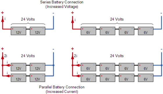 6.4.6 State-of-Charge (SOC)
This is the amount of capacity remaining in a battery at any point in time. It is equal to 1 subtruct the depth of discharge given as a percentage.
6.4.7 Charging Cycle
– The battery is charged at constant current until the voltage reaches a predefined value.-
– The voltage is held constant while the charging current decays.
– After suitable time the charging voltage is reduced to avoid excessive gassing and loss of electrolyte.
Caution: The ideal charging cannot be achieved to a PV system, where the available power is constantly changing.
In stand-alone systems, the cycle of the battery is within 24 hours, charging during daytime and discharging at night. Typical daily discharge may range from 2 -20% of the battery capacity
7. Complete System
These components provide the interconnections and standard safety features required for any electrical power system : Sized cabling, fuses, switches, circuit breakers and meters.
7.1 Battery Over Current Protection
The output conductors of the battery bank shall be protected against over current, by fuses or DC rated circuit breakers, as follows:
– In case the battery is not be earthing both two side, protection shall be provided in both positive and negative battery leads.
– Where one side of the battery bank is earthed, protection shall be provided in the unearthed battery lead.
7.2 Disconection or Isolator Devices
The output conductors of the battery bank shall be protected against over current, by fuses or DC rated circuit breakers, as follows:
– In case the battery is not be earthing both two side, protection shall be provided in both positive and negative battery leads.
– Where one side of the battery bank is earthed, protection shall be provided in the unearthed battery lead.
Safety disconnects or switches are placed into power systems to allow equipment to be safely installed and maintained. Typically, there are four locations where disconnect devices are needed in photovoltaic systems. They are:
– Between the array and the charge regulator
– Between the regulator and the battery
– Between the battery and any DC loads or load center
– Between the battery and the inverter.
7.3 Meters
Essentially two types of meters are used in PV systems:
– Utility Kilowatt-hour Meter: Measuring electricity imported and exported from/to grid (when the energy generation is not meet the energy demand or not)
– System meter: To display the charge of the battery bank, production of electricity from solar panels and amount of electricity in use. Modern charge controllers incorporate system monitoring functions and so a separate system meter may not be necessary.
7.4 Surge Protection
Surge protectors help to protect your system from power surges that may occur if the PV system or nearby power lines are struck by lightning. A power surge is an increase in voltage significantly above the design voltage
7.5 Earthing & Grounding
Earthing is the procedure where one or more parts of an electrical system are physically connected to ground, which is considered to have zero volt potential. Whereas in “Grounding” the circuit is not physically connected to ground, but its potential is zero with respect to other points. The key differences are:

All components of PV system and any exposed metal, including equipment boxes, receptacles, appliance frames and PV mounting equipment should connect to a grounding electrode (the metallic device used to make actual contact with earth). An equipment-grounding conductor is a conductor that does not normally carry current and is connected to earth.
Earthing is an important safety requirement to prevent electrical shocks caused by a ground fault. A ground fault occurs when a current-carrying conductor comes into contact with the frame or chassis of an appliance or electrical box.
7.6 Cables & Wiring
Three crucial parameters must be considered when sizing the cables:
– Cable voltage ratings
– Current rating of the cable
– Minimizing of cable losses
7.7 Bypass Diodes
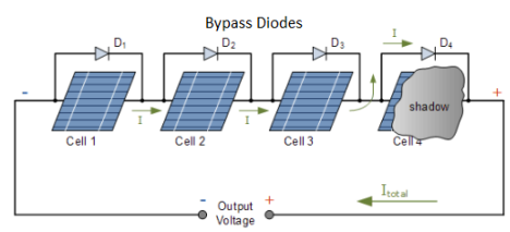
When a cell in photovoltaic module is damaged or a part of module is shaded, the shaded cells will not be able to produce as much current as the un-shaded cells. Since all the cells are connected in series, The damaged cell that will now act as a resistance make the energy generated in the module will be lost. This can be avoided by using a bypass diode in the module in parallel to the output terminal as shown in the diagram below:
7.8 Blocking Diodes
During daylight, an array has more voltage potential than the battery, so current flows from the array into the battery. But at night, the module potential drops to zero, and the battery could discharge all night backwards through the module. This would not be harmful to the module but would result in loss of precious energy from the battery bank. Diodes placed in the circuit between the module and the battery can block any nighttime leakage flow.  The lecture ends here. Hopefully it has provided you with useful knowledge about the concepts and details of the solar system. In the next lesson, we will design a complete system. See you!