I. What is the power factor (PF)?
1.1. Special electrical requirement of inductive loads
Most loads in modern electrical distribution systems are inductive Examples include motors, transformers, gaseous tube lighting ballasts and induction furnaces Inductive loads need a magnetic field to operate.
Inductive loads require two kinds of current:
• Working power (kW) to perform the actual work of creating heat, light, motion, machine output and so on
• Reactive power (kVAR) to sustain the magnetic field
Working power consumes watts and can be read on a wattmeter It is measured in kilowatts (kW) Reactive power doesn’t perform useful “work,” but circulates between the generator and the load It places a heavier drain on the power source, as well as on the power source’s distribution system Reactive power is measured in kilovolt-amperes-reactive (kVAR)
Working power and reactive power together make up apparent power Apparent power is measured in kilovolt-amp
eres (kVA).

1.2. Fudamentals of PF
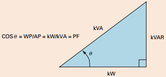
Power factor is the ratio of working power to apparent power It measures how effectively electrical power is being used A high power factor signals efficient utilization of electrical power, while a low power factor indicates poor utilization of electrical power.
To determine power factor (PF), divide working power (kW) by apparent power (kVA) In a linear or sinusoidal system, the result is also referred to as the cosine θ.
PF= Working Power (WP) / Apparent Power (AP) = kW/kVA = cosine θ
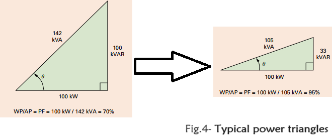
You can improve power factor by adding power factor correction capacitors to your plant distribution system.Folowing example in Fig.4 show that when power factor improved to 95% line current reduced to 11%. Its mean capacitors as kVAR generators.

II. What will happen with power factor correction
Power capacitors provide many benefits:
– Reduced electric utility bills
– Improved voltage
– Reduced losses
2.1. Reduced electric utility bills
Your electric utility provides working (kW) and reactive power (kVAR) to your plant in the form of apparent power (kVA) While reactive power (kVAR) doesn’t register on kW demand or kW hour meters, the utility’s transmission and distribution system must be large enough to provide the total power Utilities have various ways of passing the expense of larger generators, transformers, cables and switches along to you
Example: Assume an uncorrected 460 kVA demand, 480 V, three-phase at 0,87 power factor (normally good)
Billing: $4,75/kVA demand and Correct to 0,97 power factor
Solution:
kVA × power factor = kW
460 × 0,87 = 400 kW actual demand
As we known that to correct power factor from 0,87 to 0,97 requires capacitor: \[kVAR = kW.(tg{\theta _1} – tg{\theta _2}) = 400.(tg29,54 – tg14,7) = 0,316\] 0,316 x 400 kW = 110 kVAR (use 140 kVAR)
Uncorrected original billing:
Corrected new billing:
412 kVA × $4,75 = $1957/month
140 kVAR, 480 V capacitor cost: $1600 (installation extra). This capacitor pays for itself in less than eight months .
 2.2. Improved voltage conditions
Low voltage, resulting from excessive current draw, causes motors to be sluggish and overheated As power factor decreases, total line current increases, causing further voltage drop By adding capacitors to your system and improving voltage, you get more efficient motor performance and longer motor life.
2.3. Reduced losses
Losses caused by poor power factor are due to reactive current flowing in the system These are watt-related charges and can be eliminated through power factor correction Power loss (watts) in a distribution system is calculated by squaring the current and multiplying it by the circuit resistance to calculate loss reduction:
III. How can select right capacitors for specific application?
Once you’ve decided that your facility can benefit from power factor correction, you’ll need to choose the optimum type, size and number of capacitors for your plant
There are two basic types of capacitor installations:
• Individual capacitors on linear or sinusoidal loads
• Banks of fixed or automatically switched capacitors at the feeder or substation.
3.1. Individual and banked installation
– Advantages of individual capacitors at the load:
• Complete control; capacitors cannot cause problems on the line during light load conditions
• No need for separate switching; motor always operates with capacitor
• Improved motor performance due to more efficient power use and reduces voltage drops
• Motors and capacitors can be easily relocated together
• Easier to select the right capacitor for the load
• Reduced line losses
• Increased system capacity
– Advantages of bank installations at the feeder or substation:
• Lower cost per kVAR
• Total plant power factor improved—reduces or eliminates all forms of kVAR charges
• Automatic switching ensures exact amount of power factor correction, eliminates over-capacitance and resulting overvoltages
3.2. Consider the particular needs of your plant
If deciding which type of capacitor installation best meets your needs, you’ll have to weigh the advantages and disadvantages of each and consider several plant variables, including load type, load size, load constancy, load capacity, motor starting methods and manner of utility billing
-Load type
If your plant has many large motors, 50 hp and above, it is usually economical to install one capacitor per motor and switch the capacitor and motor together If your plant consists of many small motors, 1/2 to 25 hp, you can group the motors and install one capacitor at a central point in the distribution system Often, the best solution for plants with large and small motors is to use both types of capacitor installations
-Load size
Facilities with large loads benefit from a combination of individual load, group load and banks of fixed and automatically-switched capacitor units A small facility, on the other hand, may require only one capacitor at the control board
Sometimes, only an isolated trouble spot requires power factor correction This may be the case if your plant has welding machines, induction heaters or DC drives If a particular feeder serving a low power factor load is correct, it may raise overall plant power factor enough that additional capacitors are unnecessary.
IV. Calculate demand KVAR
The unit for rating power factor capacitors is a kVAR, equal to 1000 volt-amperes of reactive power The kVAR rating signifies how much reactive power the capacitor will provide
4.1. Sizing capacitors for individual motor loads
Make size capacitors for individual motor loads, use Table 1 on the following page Simply look up the type of motor frame, RPM and horsepower The charts indicate the kVAR rating you need to bring power factor to 95% The charts also indicate how much current is reduced when installing capacitor.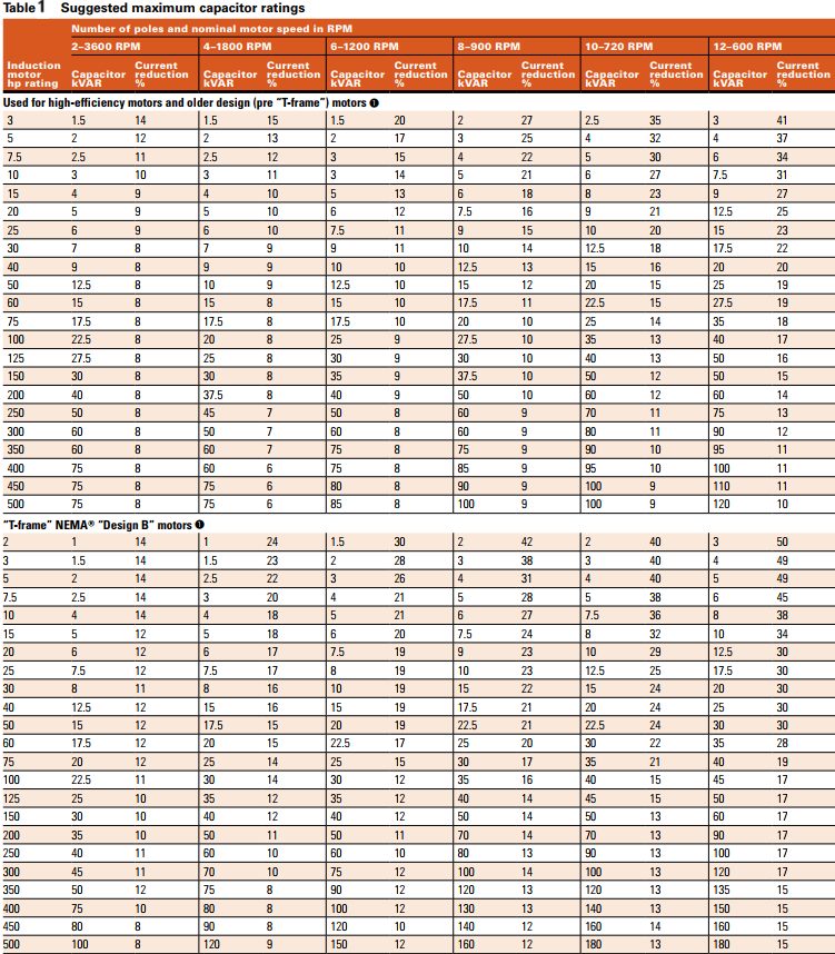
4.2. Sizing capacitors for entire plant loads
To calculate kVAR required to correct power factor to a specific target value, use the following formula:
 Where:
KW is rated active power of motor on nameplate
EFF is the motor nameplate efficiency
PFa is the motor nameplate actual power factor
PFt is the target power factor
V. Where should install capacitors?
5.1. Install at the load
Because capacitors act as kVAR generators, the most efficient place to install them is directly at the motor, where kVAR will consume three options exist for installing capacitors at the motor as flowing:
– Location A: Motor side of overload relay
• New motor installations in which overloads will size in accordance with reducing current draw
• Existing motors when no overload change is required
– Location B: line side of starter
• Existing motors when overload rating surpasses code
– Location C: line side of starter
• Motors that are jogged, plugged, reversed
• Multi-speed motors
• Starters with open transition and starters that disconnect/reconnect capacitor during cycle
• Motors that start frequently
• Motor loads with high inertia, where disconnecting the motor with the capacitor can turn the motor into a self-excited generator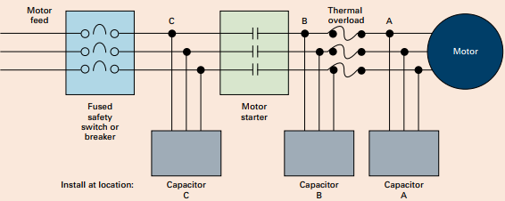
5.2. At the service feeder
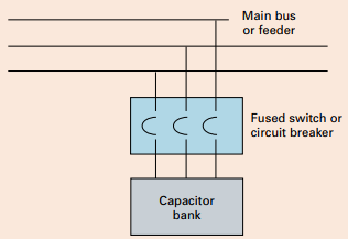 When correcting entire plant loads, capacitor banks must install at the service entrance, if load conditions and transformer size permit If the amount of correction is too large, some capacitors can be installed at individual motors or branch circuits.When capacitors connect to the bus, feeder, motor control center or switchboard, a disconnect and overcurrent protection must provide.
Hope to this lession is useful for you, If having any question and topic need to make clearly. Leave comment bellow for me. Thanks and love!
Total Readers: 467