An inductor is an element that produces self-induction when the current flowing through it changes.
When the current through the inductor changes, it will create a changing magnetic flux and an electromotive force will be induced right in the inductor or an electromotive force can be induced to the inductor next to it.
The degree of induction in each case depends on the self-inductance of the inductor or the mutual inductance between the two inductors.
Inductors are constructed to have a specified inductance value.
Inductors can also be connected in series or parallel. Even the shortest length of wire can induce a current.
Inductors usually have 3 basic core types:
– Ferrite core coil
– Iron core coil
– Air core coil
Below are 3 basic technical parameters we should remember of an inductor:
– Inductance (L);
– Quality factor of inductor (Q);
– Limited operating frequency (f g.h ).
Inductor (L)
\[{\rm{L = \mu }}{\rm{.}}{{\rm{N}}^{\rm{2}}}{\rm{.}}\frac{{\rm{S}}}{{\rm{l}}}\]
In there:
– S – cross section of coil (m2)
– N – number of turns
– l – length of coil (m)
– μ – absolute permeability of core material (H/ m); μ = μ r . μ
Units of inductance: μH, mH, H…
Absolute permeability of some materials:
-
Vacuum: 4π x 10-7 H/m
-
Ferrite T38 1.26×10⁻² H/m
-
Air: 1.257×10⁻⁶ H/m
-
Ferrite U M33 9.42×10⁻⁴ H/m
-
Nickel 7.54×10⁻⁴ H/m
-
Iron 6.28×10⁻³ H/m
-
Silicon GO steel 5.03×10⁻² H/m
supermalloy 1.26 H/m
Tolerance of inductance:
Is a parameter indicating the accuracy of the actual inductance compared to its nominal value.
\[\frac{{{L_{t.t}} – {L_{d.d}}}}{{{L_{d.d}}}}.100{\raise0.5ex\hbox{$\scriptstyle 0$}
\kern-0.1em/\kern-0.15em
\lower0.25ex\hbox{$\scriptstyle 0$}}\]
An ideal inductor has no losses when current flows through it, in reality there are always losses due to the electrical power lost to heat the coil.
This loss is represented by the loss resistor ${{\rm{R}}_{\rm{s}}}$
Inductor quality factor (Q)
Q is used to evaluate the quality of the inductor.
Small loss inductors use series equivalent diagrams, large loss inductors use parallel equivalent diagrams.

Limited operating frequency (f g.h )
When the working frequency is small, the distributed capacitance between the turns of the inductor is neglected, but when working at high frequencies this capacitance is significant.
Therefore at high enough frequencies the inductor becomes a parallel resonant circuit.
The resonant frequency of this parallel resonant circuit is called the natural resonant frequency of the coil f
If the coil operates at a frequency > this resonant frequency, the coil carries more capacitance.
Therefore the highest operating frequency of the coil must be lower than its natural resonant frequency.

HOW TO WRITE AND READ PARAMETERS ON INDUCTOR L
Direct recording: how to record full parameters of inductance L, tolerance, type of inductor core…
This method is only used for large sized inductors.
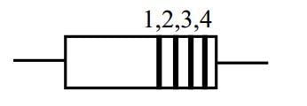
Indirectly recorded according to color convention:
For small inductors
-
Color circle 1: first significant digit or decimal point
-
Color circle 2: second significant digit or decimal point
-
Color ring 3: index 0 to be added, unit of measurement is μH
-
Color circle 4: indicates

CLASSIFICATION AND APPLICATION OF INDUCTORS
Based on application:
– Resonant coil – They used in LC resonant circuits
– Filter coil – They used in DC filters.
– Choke coils are used to block high frequency currents, etc.
Based on the core type of the inductor:
– Air core coil: A type of coil without a core or wound on non-magnetic cores, often used as resonant coils working at high and ultra-high frequencies.
Main requirements: inductance must be stable at working frequency, high Q, small specific capacitance, low temperature coefficient of inductance
– Iron dust core type: Using pure iron powder mixed with non-magnetic binder as inductor core, often used at high and medium frequencies. The dust iron core coil has low loss, especially eddy current loss, and much lower permeability than the ferromagnetic core type.
– Ferrite core type: usually inductors working at high and intermediate frequencies.
Ferrite cores come in many different shapes such as: bars, tubes, E-shapes, C-shapes, toroids, pots, beans, etc. Using a toroidal core makes it easy to create high inductance, but it is also susceptible to magnetic saturation when there is a DC component. Ferromagnetic core inductor: The core of the inductor is usually an iron-silicon, or iron-nickel compound….Some work at low frequencies. Use enameled insulated copper wire wound into multiple layers with insulation between layers and impregnated with moisture-proofing.